
UPDATE:
This project was so overwhelmingly well received that it has spawned a commercial interest. The version available for purchase varies somewhat in it's flash patterns and also in the ability to record and play back your own flash patterns. If you would like to check it out take a look at Betelgeuse - A Programmable LED Brake Lamp at my new company Lakeside Electronics, LLC.
I Purchased a motorcycle about two weeks ago. Interestingly, whenever I tell someone this news, they immediately proceed to tell me the most gruesome injuries and stomach turning plights that they or someone they know, has fallen victim to while motorcycling. In some cases, these raconteur's briefly pause to look over their shoulder, presumably scanning for small children or otherwise offendable ears, before delivering the goriest details.
One commonality in these stories, aside from the macabre and arguably poor timing involved in telling them to me is that many accidents come down to a lack of visibility of motorcycles and their riders. Less than Argus-eyed motorists often pull out into the path of a motorcycle and with insufficient time for evasive action, that quickly an accident has occurred. Other times, drivers may focus on the car ahead of the motorcycle and in the event of stopping at a red light or similar, fail to leave enough room for the motorcycle, unfortunately rear ending him or her.
In the photo below, you can see that I am in one piece and the bike is also. Let's see what we can do to help keep things that way.

To partially combat the lack of visibility I decided to make a replacement brake light for my bike; one that would strobe briefly when I applied the brakes then stay solid on. I got this idea when I noticed a similar strobing effect to the brake lights on an ambulance that I was following near to, but not immediately behind. Those lights really got me to notice the ambulance which I had largely ignored up until that point.
I would also want a way to be able to disable the brief flash before the brake light stays solid on. This could be useful if the flash was ever to cause a safety hazard to other drivers or if I am ever stopped by the police for having this system I can easily disable the strobe part and still have a functioning brake light; I do not want to be stranded. I wrote the software so that if you turn the key on while you have the brakes applied, the flash is disabled. You must turn the key off, then back on, without the brake applied to restore the flash functionality.
Here is a video of the prototype Tenty LED Brake Light installed and operating. In the video, I demonstrate the flashing brake light 3 times and then key off. Then I disable the strobing part by turning the key on while holding the brake on, demonstrate that several times and key off again. Finally I re-enable the strobing functionality by key on with the brake off. For the purposes of the video, I lengthened the duration of the flash on and off times. This is so the camera can better capture the flashes.
In order to keep this system reversible should I ever have the need to put it back to stock, here is how I mounted the circuit board inside the tail light lens. I bought some replacement bulbs at a local auto parts store, broke out the glass and desoldered the filament. I replaced the filament by soldering wires to the tail light power, brake light power and ground. I ran a file over the solder blobs just enough to level them out so they would make good contact with the socket. I then filled the bayonet base with epoxy and inserted an 8-32 stainless steel screw into the base being careful not to touch the screw to any metal, accidentally making the screw a conductor. Below are a few pictures of this process.
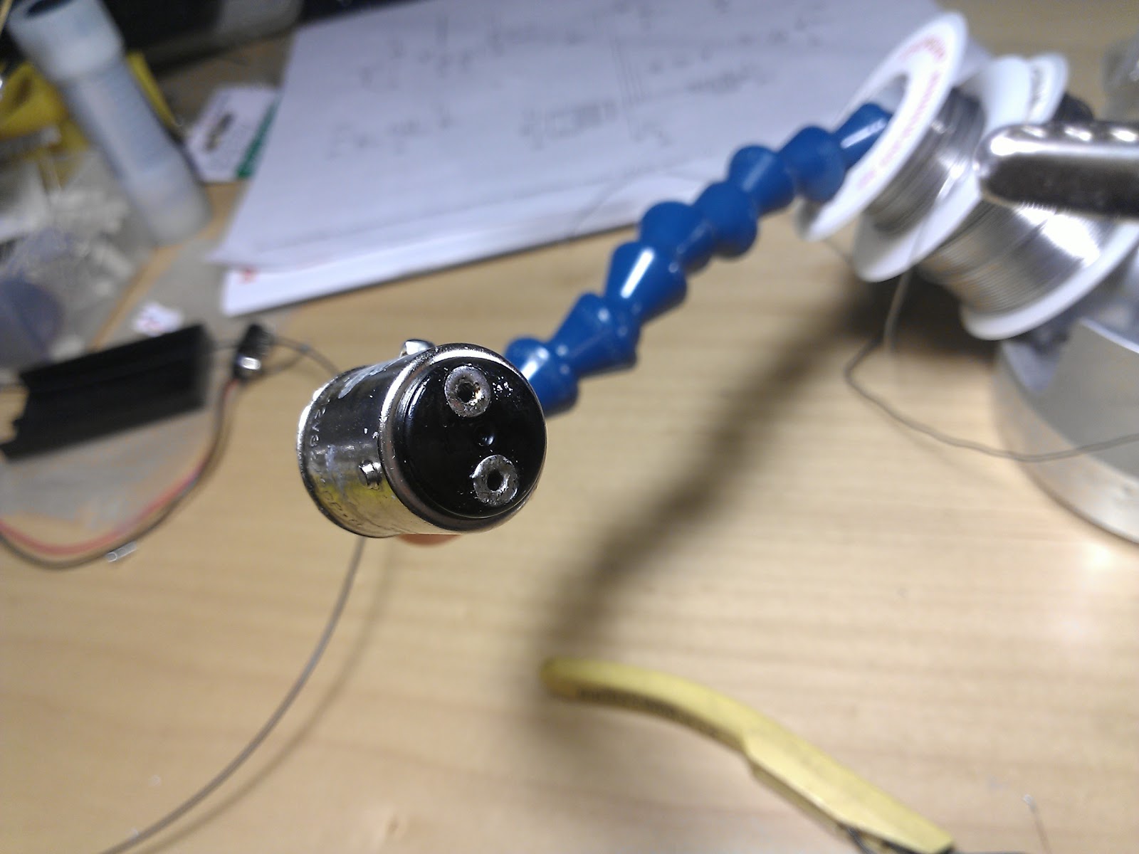


After installing the modified bayonet screw mounts I threaded two nuts on each and jammed them together. This is what the back of the circuit board will rest on. You can see several pictures of the final assembly below.


Circuit:
The circuit is basically a large array of really bright red LED's ( Light Engine ) and an ATTiny85 microcontroller to tell the LED light engine how to behave. There are also two high brightness LED's that shine downward onto the license plate. They are solid on all the time as required by the Michigan vehicle code. The red LED's, made by Optek have a 100 degree viewing angle and output 8000 mlm each - there are 16 of them. The brake light switch delivers it's ~12 V signal translated thru an 2n3904 transistor to pull a microcontroller pin low. I usually use 14.4 V when doing calculations for operating voltage on 12V systems like this. Total current draw with all LED's at maximum brightness is less than 500 mA. I ordered the logic level mosfet IRLU3410PBF from mouser.com also, which is used for the PWM control of the light engine. Below you will find a screen cap pic of the schematic.

Software
There are two modes of operation to this brake light - flashing and non flashing. The non flashing brake light is activated by turning the key on while holding the brake and behaves just like a stock brake light would. Flashing mode is enabled by default so key on with brake off and you are good to go. In this mode, the LED light engine strobes briefly upon initial application of the brake then is a steady on light. I set the period of the flashes to be higher for the videos so the camera could pick them up, you can see in the code below that the flash period is twice as fast in the operational version of the software. Feel free to use the code as you see fit.
/*
Program Description:

This program controls an LED light engine used as a brake light on a motorcycle.
When the brakes are applied the tail light flashes several times off then on before
being a steady on brake light.

The program also has a feature to disable the flashing brake light and the brake light will
behave like a standard lamp ie no flashing.  This mode is enabled ( flash mode disabled )
by turning the motorcycles key on while holding the brake on.  The state is reset after a power
cycle.

Legal Note:  I read the entire vehicle code for my state.  It does not address brake light flashers, but
does prohibit " rotating, oscillating or flashing red lights ".  I believe a brake light flasher
differs from " rotating, oscillating and flashing " lights in the implied duration of operation.
My state did not respond to emails I sent requesting clarification.
Basically, modify your vehicle at your own risk.

Change Log
2012.4.21 - added 1 mS debounce to brake switch in main loop - Pete


A circuit description and other details can be found at http://petemills.blogspot.com

Filename: led_brakelight_main.c
Author: Pete Mills
petemills.blogspot.com
2012.4.15

Int. RC Osc. 8 MHz; Start-up time PWRDWN/RESET: 6 CK/14 CK + 64 ms

*/


//********** Includes **********

#include <avr/io.h>
#include <util/delay.h>


//********** Definitions **********

// Output to LED Light Engine

#define LED   PB0
#define LED_PORT PORTB
#define LED_DDR  DDRB


// Input for Brake Switch

#define BRAKE_SWITCH  PINB4  // bit is clear when brake switch is pressed
#define BRAKE_SWITCH_PORT PINB
#define BRAKE_SWITCH_DDR DDRB


// PWM Preset Values

#define TAIL_LIGHT_PWM  25
#define BRAKE_LIGHT_PWM  255


//********** Function Prototypes **********

void setup( void );
void brake_alert( uint8_t number_of_flashes );


//********** Global Variables **********

uint8_t disable_flash = 0; // if 1, the flashing part of the brake light will be disabled


int main(void)
{


setup();

_delay_ms( 5 );


// if the brake light is held on during boot up, disable the flashing
// flashing can only be disabled during boot up ( key on ) and is reset after power down ( key off )
// this could be useful if you suddenly learn your flashing light is causing a problem for other motorists
// or citizens employed to monitor the adherence to legislation and cite violations for deviation from such


if ( bit_is_clear( BRAKE_SWITCH_PORT, BRAKE_SWITCH ) )
{
 disable_flash = 1;
}


 while(1)
 {


  if ( bit_is_clear( BRAKE_SWITCH_PORT, BRAKE_SWITCH ) )  // if the brakes are applied
  {

   _delay_ms( 1 ); // filter time aka debounce

   if ( bit_is_clear( BRAKE_SWITCH_PORT, BRAKE_SWITCH ) )  // if the brakes are actually applied
   {

   // if we are allowed to flash, do

   if( disable_flash == 0 )
   {
    brake_alert( 5 );
   }


   // if the brakes are still applied, hold the LED light engine to a brighter output
   // until you release the brakes

   while( bit_is_clear( BRAKE_SWITCH_PORT, BRAKE_SWITCH ) )
   {
    OCR0A = BRAKE_LIGHT_PWM;
   }

   _delay_ms( 100 ); // debounce the brake switch release ( break )

   }

  }

  OCR0A = TAIL_LIGHT_PWM;  // restore the tail light on


  /*
  // demo mode
  for( ;; )
  {
  brake_alert(6);
  OCR0A = BRAKE_LIGHT_PWM;
  _delay_ms(2000);
  OCR0A = TAIL_LIGHT_PWM;
  _delay_ms(4000);
  }
  */

 }
}


//********** Functions **********

void setup(void)
{


 //********* Port Config *********

 LED_DDR |= ( 1 << LED);   // set PB0 to "1" for output
 LED_PORT &= ~( 1 << LED );   // turn the led light engine off

 BRAKE_SWITCH_DDR &= ~( 1 << BRAKE_SWITCH );   // set BRAKE_SWITCH pin to 0 for input
 BRAKE_SWITCH_PORT |= ( 1 << BRAKE_SWITCH );   // write a 1 to BRAKE_SWITCH to enable the internal pullup


 //********** PWM Config *********

 TCCR0A |= ( ( 1 << COM0A1 ) | ( 1 << WGM01 ) | ( 1 << WGM00 ) ); // non inverting fast pwm
 TCCR0B |= ( 1 << CS00 ); // start the timer


}


void brake_alert( uint8_t number_of_flashes )
{
 // here we create a visual alert that the brakes have been applied
 // pass this function the number of flashes desired ( off then on = 1 )

 //uint8_t delay_between_flashes = 50; // for video demonstration purposes ( video aliasing issues )
 uint8_t delay_between_flashes = 25; // every day use
 uint8_t alert_pwm_min = 2;   // minimum and max values to flash between during the alert
 uint8_t alert_pwm_max = 255;


 for( int i = 0; i < number_of_flashes; i++ )
 {
  OCR0A = alert_pwm_min;
  _delay_ms( delay_between_flashes );
  OCR0A = alert_pwm_max;
  _delay_ms( delay_between_flashes );
 }

}
Legal Note:
I'm not too sure what to say about the legality of this project. I read the entire vehicle code for my state. There was no reference to brake light flashers for cars or motorcycles. The vehicle code for Michigan does prohibit " rotating, oscillating or flashing lights " on non-emergency vehicles, however I believe my brake light does not qualify as the clear intent in the vehicle code was " rotating, oscillating or flashing " lights that continue to do so for an extended period of time as emergency or police vehicles do. Really, my device is no different than tapping your brake pedal several times before stopping your motorcycle. In the end, I did send an email to the state of Michigan requesting clarification. At the time of this writing there has been no response. I think the bottom line is, don't modify your vehicle unless you are willing to accept full responsibility for any outcome.
Here are a couple pictures of the build process. The abstract looking pictures are of the LED light engine shining thru my desk magnifier onto the ceiling.


Comments
Consider a headlight modulator as well as good protective gear.
but that break strobe made me put that mod in my to-do list! damn you
While I REALLY want the modulator that does this for me (you can buy a harness thats practically PnP) My hand does a cheaper job ^_^
Nice write up. Now you have me thinking about turn signals too. Maybe tri color Gr/Yl/Rd leds for yellow turn and red brake when the turn isn't activated. Have to do some thinking on that.
I think I'm going to copy your concept and adapt it for my bike.
If you have easy access to your tail lamp, I would take a Sharpie, either red or black and go over the board. That way it will show less while the lamp is off :)
I think porting the brake light project to an arduino would be a great project! Provided that your bike is also a ~12 v system you could just replace the ATTiny85 I used with the ATMega running the arduino boot loader. You can probably sort out that you need to connect the ATMega pins appropriately, connecting the ATMEGA PWM output pin of your choice to the logic level mosfet in the original schematic.
One improvement for this circuit would be to replace T1 ( 2n3904 transistor ) with an optocoupler. I didn't have any at the time but have since purchased these and will install one when I have time. http://www.sparkfun.com/products/314
I have also added a 0.1uF electrolytic capacitor on the output of the 5 v regulator and this helps keep the power supply stable during transient responses.
When you write your code keep safety in mind. The same is true for making the hardware. A brake light is an important device that must be 100% reliable.
If you have any questions feel free to email.
Best of luck and let me know how it turns out!
-Pete
Just did the build my self for my Ducati 900ss, and it all worked out great, thx to the pictures on your site, and the code.
Pictures can be found here:
http://juelsminde.org/?p=6&lang=en-us
im not very good in software programming, just a little bit knowledge of soldering component here and there..
But im not intend to install it on my bike but i want to install it on my car...not just the 3rd brake light but also the Left/Right brake light.
1 kit is enough but it may take to many wire..so prefer 2 kits for each L/R brake light..independantly.
Just my opinion.
Im from Malaysia BTW.
I do not sell kits for this brake light, but I did recently release a similar product for sale here.
http://lakesideelectronics.net/?wpsc-product=betelguese-a-programmable-led-brake-lamp
Good luck with your project. It sounds like it will look very cool!
-Pete
I adapted it to fit my Yamaha VStar.
I also used my arduino uno to program the tiny85.
The bikes existing electrical system does a pretty good job of smoothing out any voltage ripple or spikes so no additional protection was employed. Of course, as you saw in the schematic, there is a voltage regulator for the ATTiny85.
I'm glad I came across this site. I made this my first real electronics project and built a version of this circuit for my Yamaha WR250X. I learned tons about programming for an Arduino and even loaded my code to an ATTiny 45. It works awesome!!!
Thanks for the inspiration.
MarkC
I very new for electronic.
Your project is great. I try to do it . It work OK on breadboard but not work on my small honda bike 125 cc.
I measure voltage from engine is around 4-5 V. Voltage signal from brake is 12 V.
Could you advise how should I do . Thank in advance.
:) Krit
Congratulations on getting your circuit working on the bench!
I am not sure where you are measuring the 4-5 V power from, but the circuit I designed will need at least 7 volts to run reliably.
I know some motorbikes don't have alternators and rely on other means of generating very noisy electrical power.
Perhaps if you find the source of the 12 V brake light signal you will find a suitable power supply.
Best of luck!
Pete
Krit
IC1 is a 7805 voltage regulator. Good luck with your project. Write in when you get it done!
-Pete
A 7805 is capable of generating enough heat to trip its internal thermal limit and shut itself down prior to damage.
This occurs when we are regulating high currents from high voltages.
To combat this you would put a heat sink on the 7805 to keep it cool.
Basically I try to keep most things below 50 deg C.
So, lets take a look at the LM7805 datasheet. It says it has a thermal resistance for junction to air of 65 deg C per Watt. This means that if ( (input voltage - output voltage) * output current * 65 C/W + ambient Temperature > 50 C we will use a heat sink.
For example ((9vin - 5vout) * .1A * 65c/w) + 21c = 47 deg c. So, we are ok if we don't go above 9v input with 100 mA output current.
-Pete
What are your thoughts on using this to replace the 7805: http://www.adafruit.com/products/1065
The regulator you linked to would be good for higher current projects. This circuit uses very little current on the 5 V supply. All of the LED current is supplied directly from the vehicle battery.
Please forgive my prior example. I chose poor numbers to illustrate what is necessary, so let me try again.
Since your alternator runs at about 14.4V and the only current on our 5V rail is the AVR which we will say is (much) less than 1mA we can calculate: ((14.4 V - 5 V) * 0.001 A * 65 c/W ) = 0.61 C temperature rise.
You are fine to use a 7805 here on the nominal 12 V motorcycle battery. I suspect when you had a hot 7805 before, you were passing a lot more current thru it...
I am also a new motorcycle rider, I will building for a 2004 ninja 250. The LEDs are on back order.. hopefully I'll get the items soon.
Thanks
I did not use an arduino bootloader.
-Pete
That is a nice bike you have. Be sure to send some pictures when you get your tail light done. I'll post them up here.
Ride safe!
-Pete
Thank you, Fred
I use an ATMEL AVR ISP MK2 and avrdude.
-Pete
Fred
I am not sure if you are asking if my program will work on an ATTiny85 with arduino bootloader or if you are asking if you can program a bare ATTiny85 with my code using an arduino as an ISP.
The answer to the former is simply, no. The slightly longer answer to the latter is: I think so, but I have never done it."
I suspect that if an arduino can be used as an ISP to burn a boot loader ( and I believe it can ) that it can probably be used to flash "tenty brakes" to a blank AVR as well.
If you dont find a definitive answer, email me and I can send you a programmed ATTiny85 if you like.
-Pete
Fred
Fred