A little while ago a writer for Popular Science magazine approached me asking if I would be interested in collaborating with them write a " How To " article based on my Clever Clapper post the other month. Well, of course I would, that sounds awesome! And so, I made another Clapper lamp, this time leaving out the laser activated moon lamp so as to better fit the magazine space.
Clapper Demo
Party Mode Demo
Fast forward a few months and you can find in the June 2012 issue, the " Diy Clapper " article on page 80. You can see an online version of the article and links to software etc on the Popular Science page here.
All in all, it was a pretty cool experience, but I am left with another clapper lamp now. And worse, dueling clapper lamps that have no mechanism by which to synchronize themselves. Two claps may or may not turn on both the new clapper lamp and original Clever Clapper leaving me with flip flopping lights until I have to resort to manual control of one or the other lamp.
The non-necessity of having multiple clap activated lamps in my house prompted me to make an LED Stroboscope with the latest lamp - utilizing as much of the hardware as possible. I only added a potentiometer to set the strobe frequency.
I would not design a stroboscope with this hardware from scratch, but it is a good reuse of the lamp and circuit that would otherwise sit idle. For instance, a fairly big drawback is the 8-bit timer in the ATTiny85. The frequency step changes are quite noticeable and I would prefer a 16-bit timer like the ATMega328 has.
And of course with those extra uC pins I could add a display to show the frequency rather than relying on an oscilloscope for measuring the output frequency. Having said that however, with a lack of crystal on the ATTiny85, using the internal RC oscillator instead, it is probably better to measure the frequency externally rather than an internally calculated frequency display.
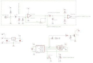
You can see the hardware changes from the Clapper lamp outlined in the schematic below. I disconnected a few connections and added a potentiometer, that's about it.
The software for the stroboscope can be downloaded here. It isn't the prettiest of code as, but it should suffice until I can build another stroboscope with a more concentrated effort.
To operate the stroboscope you just turn it on and the lamp is strobing somewhere between ~4 Hz and ~31.3 kHz. The maximum flash rate is high enough so as not to be noticed. So you can use it as a reading lamp. Pressing the tactile switch shuffles thru a loop, changing the timer presets thus decreasing the flash rate by 2 times, each press until it loops back to the beginning. Find your range with the tact switch then turn the potentiometer to set the exact frequency required to stop motion.
In the video below, there are on screen comments noting the points where the strobe frequency is a multiple of the fan speed. It is advantageous to use a mark on symmetrical parts to determine when the strobe frequency is a multiple of the part frequency or spot on. I marked this fan blade with a sharpie so I know that if the rotational motion appears stopped and I see two arrows ( sharpie marks ) then the strobe frequency is 2x the fan speed. It should follow that one sharpie mark showing means the strobe is 1x the fan speed. This is the basic principle of stroboscopes, but for a more in depth look have a look at this wikipedia entry.
I am pretty pleased with the results and knowing the limitations of this stroboscope I can still see it being useful to me. Of course I look forward to making a more full featured model with improved timer hardware etc, but for now I can inspect all kinds of rotating or oscillating mechanical bits in pseudo slow motion. I can also measure the speed of unknown objects easily as well as prototype some zoetropes or similar.
As an aside, have a look at this scope my Mother bought me out of the blue the other day - just in time to use it for this project too! How cool is that?


Comments