An Arduino, some addressable LED's, a bluetooth module, code and a 3D printer come together to make blueShift - An OpenXC LED Tachometer. blueShift is so named for the Bluetooth protocol used for data communication, and the use of a tachometer to indicate when to shift your car. It may be amusing to note that the driver and passengers traveling in this car would observe Blueshift when peering thru the windscreen, provided their velocity was sufficient.


It took a couple days driving around to figure out all the bells, whistles, and electronic gizmos in the Fiesta, and just that quickly, I was looking for something more. What that turned out to be was Ford's OpenXC API. OpenXC is part hardware, part software. It is open source, as the name suggests and aims to ease us into integrating vehicle data into our android apps, and in case of blueShift, embedded hardware.
Let's take a brief, but closer look at OpenXC and the potential it provides. For quite some time now, auto manufacturers have provided an OnBoard Diagnostics port. This OBD2 port, as it is sometimes called, is a digital interface to engine management parameters and chassis/body status. To the typical hobbyist, an OBD2 ports data is relatively inaccessible. You would need to know manufacturer proprietary PID's for the CAN messages you were viewing to discern "air intake temperature" from "outside air temperature" for instance. Likely, the information you were able to decode is specific to one vehicle make/model or worse, ECM batch.
Under the OpenXC umbrella, Ford has developed a hardware module called a Vehicle Interface or VI. This VI plugs into your OBD2 port, and interprets engine parameters and chassis/body info. These data are then packaged into JSON format, and relayed out over Bluetooth SPP. If you were to look at the OpenXC Data set you would discover that listening to this Bluetooth connection provides you with a plethora of vehicle specific information in real time. For instance, you can read your accelerator pedal position, fuel level, odometer, brake pedal status, and of course engine speed. The list goes on.
blueShift aims to utilize these engine speed data to drive a set of LED's in an easy to interpret, graphical manner. The circular nature of an off-the-shelf LED strip lends itself to this project nicely. What's more, these LED's are individually addressable, RGB LED's. This means that we can set any LED on the ring to just about any color we like, at any time we like. blueShift takes advantage of these addressable WS2812B LED's to create an interesting and informative display.
At first glance it may seem a second tachometer in my car is superfluous. I can say after having used blueShift, quite the opposite is true. The LED's are much easier to read with peripheral vision than the stock tachometer needle. Likewise, blueShift would be very useful for someone who races Ford automobiles. Additionally, blinky LED things are just plain cool, and no further justification for this project is therefore necessary.
The only wired connection to blueShift is for power. All data transfer is accomplished over Bluetooth SPP. Presently, this power is derived from my vehicles on-board USB power. I have plans to derive power from the OpenXC VI power port in the future. This will require a small regulator to convert the vehicle ~14 V DC to a microcontroller compatible, regulated 5 V DC supply. This supply will also need to supply power for the LED ring, so current consumption should be considered.
3D Printed Enclosure:
Sometimes a project will take you to unanticipated places. In the case of blueShift, that ended up being the land of 3D printing. Typically when I make a new project I am left to drilling and milling existing enclosures, and sometimes tupperware. What I am left with is a finished product that looks less than finished. When I was envisioning how I wanted blueShift to look, it deviated rather drastically from the prototype seen below.

Once it was decided to build a 3D printer to print blueShift's housing, I started down the path of designing a 3D printer of my own. I had a basic layout and construction method in mind when I started looking for approximate pricing on parts. I soon discovered that the constituent parts of my 3D printer design were approaching the cost of a 3D printer kit. This led me to purchase a Prusa i3v from Maker Farm, and I am glad I did. The kit was assembled in a few evenings. The decision to build a kit saved substantial time over designing a printer. The first prints were the requisite calibration cubes and then some other items. There is probably still some fiddling to do with the printer setup, but I am pretty pleased with the print quality so far.

Here is a photo of the partially finished 3D printer.

I designed the 3D models for blueShift in AutoCad 2014. I then exported the models as *.stl files and uploaded them to Thingiverse for sharing. You can download the *.stl files to print your your own blueShift enclosure, or I think companies like Shapeways may print them out for you if you don't have a printer ( yet ). I have no experience with that.
Below are some photos of the enclosure in various states of printing, and drawing revisions. The portions of the print that have large gaps and look like a lattice are intentional. This makes up supporting structure for parts with overhangs while printing. It is designed to break off easily, and in practice this is sometimes true.


I am really enjoying 3D printing. Even with it's obvious limitations, I feel that I will make good use out of this tool. I see many opportunities to print things that may or may not be necessary, but ultimately I am having a great time with it.
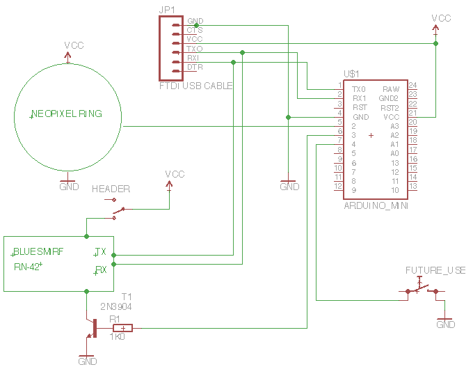
Electronics:
Part List:
- NeoPixel Ring w/ 24 WS2812 RGB LED
- Arduino Pro Mini
- BlueSMiRF Bluetooth Module
- NPN transistor + 1k0 base resistor
- Pushbutton Switch ( optional )
- FTDI cable for programming and power
- A Ford OpenXC VI
I am using an RN-42 Bluetooth module from Sparkfun called a BlueSMiRF . One of the first things to do is connect to the modem and configure it for Auto-Connect Master Mode (SM,3). The AT Command sheet will walk you thru this process. For more detailed information on how to connect the Bluetooth module, and enter into command mode, refer to the Sparkfun tutorial.
With the Bluetooth module configured, we can wire up the rest of the circuit and tuck it into the blueShift housing. Here are a few pictures that show this process. Great care should be taken to avoid short circuits. Currently I power the blueShift from an FTDI USB cable.


The little tactile switch will perform a function in future software revisions. For now, it does nothing in software.

The two red wires with header pins are for the bluetooth modem power. This is represented as a SPST switch on the schematic labeled "HEADER". It is necessary to unpower the modem when uploading new firmware to the Arduino. This should be shorted out while operating blueShift to power the Bluetooth Module, and disconnected for uploading new firmware to the arduino.

This would be a good time to install the software and verify everything works. If you need to re-solder anything, it is better to find out now. The author may have experience that lead to this warning.
In the picture below, this semi-opaque, 5mm thick disk is possibly polypropylene. I purchased the stock from an unknown bin at a shop and belt sanded it into shape. There are 3 equally spaced clearance holes drilled into this lens to accommodate the M3 mounting bolts which we are about to install. Drop the lens into the outer housing and line up the holes.

Insert the assembled and tested inner housing into the outer. Line the three M3 bolts up and screw the entire assembly together.

Screw the Ram Mount to the back of blueShift. This will now suction cup to your windshield and plug the FTDI USB cable into a USB port in your car. If you don't have a USB port onboard, there are 12 volt outlet to USB adapters available.


Software:
You can download the Arduino code here.
When blueShift first turns on, there is a brief pause. During this time, we are waiting for the Ford OpenXC VI to boot up, and for blueShift to establish a connection to the VI. For a bit of fun, we display the "Waiting for Bluetooth Throbber" that you can see below.

Once a connection is established and valid RPM data is coming thru, the display changes to "Run Mode". In this state, RPM is displayed as a green LED trail. It grows clockwise as RPM increases, with the final LED being displayed in red for a bit of visual interest.
This final LED, the highest LED displayed, is "sticky". That is to say, as your RPM begins to decay, the peak RPM read will continue to be displayed as a single red LED. This will either persist until 3 seconds have elapsed since the peak measurement or once a positive rate RPM is detected.
Since OpenXC provides with boolean headlamp status on the same bluetooth connection, we can implement auto-dimming of blueShift. As soon as your headlamps come on, blueShift will dim. When your headlamps return to the off state, blueShift will regain full brightness. This is not just a nicety - it is rather important. These LED are quite bright and without dimming at night the result is a well lit car interior.
The sticky LED telltale can be seen in the video below. You can also see the auto-dimming feature towards the end of the video. It's a little hard to see when the headlights turn on because its still light out, but you can see blueShift get dimmer. You can also hear the headlight knob click on.
At the time of this writing, blueShift is hard coded to a specific RPM span. That is to say, if you wanted the first LED to light at 500 RPM and the final LED to light at 6000 RPM, you would need to reflash the firmware. After I get a few more miles on my car I will want to change that so, I will probably use that tactile switch as a way to program the RPM span without reflashing firmware.
To implement this I think it would be good to have a "programming mode" where say you enter program mode and blueShift will keep track of the highest RPM read. You press the button once to set this as the lower RPM span. Now, rev your engine and blueShift will remember the highest RPM achieved. Press the button to store this as the high RPM span. These new values will be saved to EEPROM and recalled at the next power on cycle.
Additional firmware upgrades include moving to JSON parsing. Right now I just read the full JSON line and manually parse the string for the values I want. If something were to change in the VI firmware, it is possible to break my code.
Are you making a blueShift? Send me a message, I would love to hear how it's going. Happy making!
Comments